Mechanical Engineer Intern
May 2018 – December 2018
Working for SEL evolved my education into becoming proficient in the professional world. This position greatly increased my technical and analysis skills. Prior to this internship I had little experience with tolerance analysis, but after 7 months I completed dozens of tolerance analysis.
I loved every day working at SEL because of the community feel of the workplace. They have core values that everyone there believed in and represented. The employees were all great to work with. I received a lot of positive feedback which continued to push me to do better the next day.
A daily routine working for SEL was approximently 70% using SolidWorks, 15% meeting with team members, and 15% using other software including Lotus Notes and Microsoft Office.
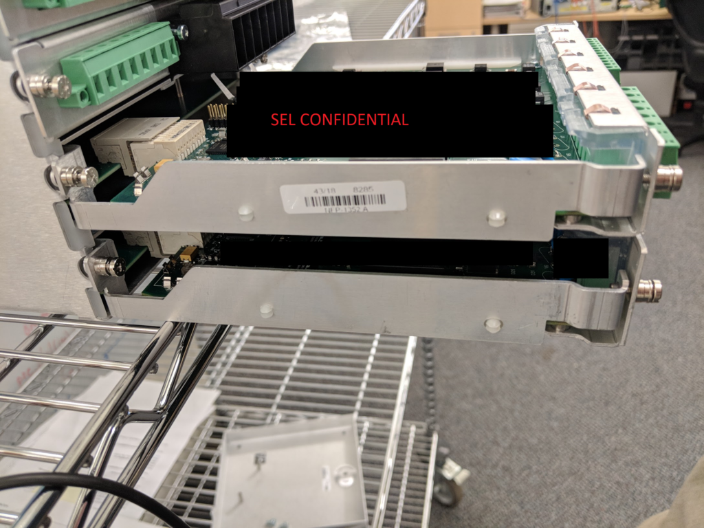
NOTE: Most of my work at SEL is confidential and could not be shared on this site.
Design
Schweitzer Engineering Laboratories introduced me to designing parts for injection molding and enhanced my skills with sheet metal parts.
Plastic Cap Project
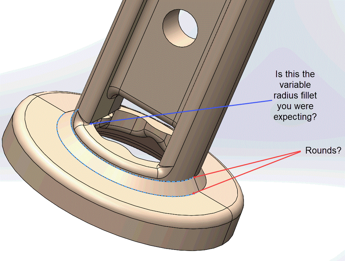
Figure 1 shows a cap that I designed to snap onto a small tactical switch. This part had many design constraints due to the tolerance stack ups in the assembly surrounding it, and the desired snapping force required. The geometry of this part also made it difficult to design for injection molding.
Through design iterations and approaching the problem with different possible solutions, I was able to create various options and recommendations. To move forward with the process I presented mechanical design reviews to a handful of engineers to see if they had any concerns. My presentation and designs led to positive feedback.
"Thank you for your persistence in arriving at a variety of possible solutions to this tricky problem. Great design review and PowerPoint presentation. As reviewers, we subjected your design to some rigorous scrutiny. I think you did a good job defending your design, and the top-pick solution is a really clever molded part design (referencing specifically the use of pass-cores)."
This part was the perfect teaching project. It was my first part designed for injection molding, but I was told I learned quickly and excelled. I am grateful for all the guidance I received from my supervisor and peers.
"You are doing a really great job here. Your final solution is very cleverly and well thought out. The jump from where your part started, to where your part is finishing, is the largest I've ever seen. I was so impressed by the jump, that I called Glen over to show him. Normally, it takes a few rounds to evolve a part like this with a new designer, so Glen and I were very pleased."

Sheet Metal Chassis
A second project was designing sheet metal chassis that were meant for in house testing equipment. This project taught me how to use PEM hardware for better hardware connection and how to hold tighter tolerances. Choosing the right hardware allowed more flexibility in design and allowed greater tolerances.
This project taught me to think of all possible future failures. When designing this part, I looked at: reducing material waste, simplicity, lightweight, loose tolerance, and more. What I did not consider is bowing in the sheet metal across 4 inches of aluminum or how much stiffness a circuit board would add to the assembly when fastened to the chassis. These simple overlooks taught me to be more observant in my future designs.
Even though the initial prototypes had a few minor setbacks, I was able to modify the parts with simple fixes that our in house clients were very pleased with.
Analysis
At SEL, my analysis focus was in FEA and tolerance, however, I also gained experience in thermal and frequency. I used FEA repeatedly in designing plastic snaps that would not yield or be too stiff. Thermal analysis was used to design heat exchanger slugs to remove heat from circuit board components to the chassis. I used frequency analysis to verify vibration testing fixtures would not have resonate frequencies within the testing range.
Testing


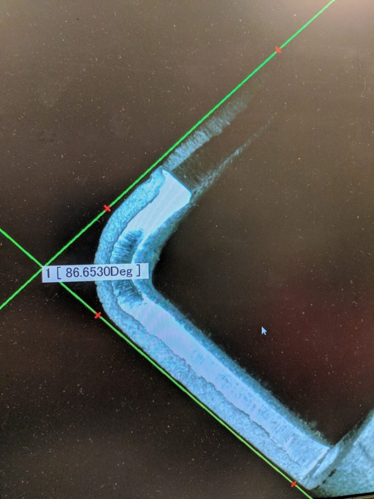
At Schweitzer Engineering Laboratories, I got the opportunity to explore new ways of testing. Figure 3 shows an image I captured while verifying angles were within tolerance.
Other tests included troubleshooting the pressure being placed on touch screens from mounting hardware and using a rotary Xray machine that allowed me to examine cracked screens and determine root causes.
Additionally, I also used a tensile machine to test the tolerance of PCB hole location and sizing. I achieved this by inserting and extracting connector pins in and out of the hole and plotting the resistant force the board exerted onto the pin.
A more common test was IP rating tests to verify the gaskets I worked on were water tight. Figure 4 shows me holding a control flow rate spraying a test fixture containing a gasket. This specific test was to validate the gasket could hold up against rain environments.
Drafting
After every part I designed I would follow up with a drawing for the machine shop or an outside vendor to produce the part. Communicating with the shop was key a to success.
I also made mechanical drawings for PCB boards to coordinate where holes needed to be and verify with the electronics depart where components will be located.
Unfortunately all drawings are SEL confidential and I cannot share them, please look at the senior design project or my 3D printers for drawing examples.

